Designing a combiner
One way of combining several antennas on VHF/UHF is by using a
so called power combiner (or power splitter if you prefer to
look at it from that angle)
Using the principle of impedance transformation in a quater wavelength
transmission line, a proper matching can be made between antennas
and the downlead cable.
To build a combiner you need to design a coaxial quaterwave line, having
a caracteristic impedance Zo, determined from Zo^2 = Z1*Z2, where Z1 and Z2
are the impedances being matched.
This is normally done by using tubing - round or square
- with air as dielectricum.
Simple impedance calculation
The caracteristic impedance for the two types of lines are: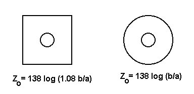
Combiners for 144, 432 and 1296 MHz
2-way combiner for 144 MHz.
4-way combiner for 432 MHz.
2-way combiner for 1296 MHz.
Exact impedance calculation
The expression for circular outer conductor is the exact solution! - but for the square outer conductor the formular is an approximation, that's only accurate for some b/a ratios (-and impedances).In the amateur litterature a number of different formulars for square outer conductors have been published. I my search for the most correct or accurate expression I have tried to trace back the origin of the different formulars.
The best formular to use is: Zo = 138 log (1,08 b/a). It works well for
impedances above approx. 20 ohm - however if you want the highest accuracy,
then instead of the factor 1.08 you can use the expression:
Have a look at W9CF's homepage for an indepth treatment of the exact solution.
The formular: Zo = 138 log 1,178 (b/a) is often seen in RSGB litterature
and quoted elsewhere. This gives a wrong result! The factor 1,178 comes
(probably) from litterature dealing with fields on the outside of a
square conductor - and not on the inside!
An attempt of deriving the exact solution was published in "The Capacity per Unit Length and Characteristic Impedance of Coaxial Cables with One Slightly Non-Circular Conductor" by Philip Parzen in "Journal of Applied Physics" Vol 18 August 1947. This led to the following expression:
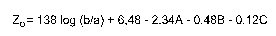
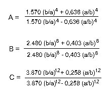
Parzen's formular was later rewritten in SAMS "Reference Data for Radio Engineers", but here errors was introduced, when attempts were made to reduce the expression for the factors A,B and C - now inaccuracy blends with errors - so beware!
Later a simplification of the formular in SAMS "Ref. Data..." has led to the formular: Zo = 143 log (b/a)+2. This is another workable approximation useful for low impedances - down to about 20 ohm.
Errors using the different approximations
With knowledges of the exact expression for transmission line impedance, an estimation of errors can be made. Errors can be due to the use of wrong formulars and (more often) having to use nearest standard size tubing.An additional source of error is the effect (on frequencies above 432 MHz) of the coax connector centerpins, which adds a small series inductance to the quaterwave transformer. This has the effect of moving the frequency of best match away from the design frequency.
With a quaterwave transformer, remember that a 10% error in the transmission line impedance is transformed to a 21% error in the "other end". It's therefore quite important to build combiners as accurate as possible.
Back to OZ2OE homepage.