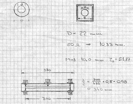
This design is a 4-way combiner made up from two quaterwave transmission lines connected together. The transmission line is therefor one halfwave long - or 340 mm. 50 ohm N-connectors for the four antennas are placed two and two at each end and in the middle another N-connector for the output.
The two quaterwave sections must transform the antenna impedance of 2 times 50 ohm
in parallel - or 25 ohm - into 100 ohm, so when paralleled in the middle a 50 ohm
impedance is again established.
The correct transmissionline impedance is the square root 25*100 or 50.0 ohm.
Diameter of center conductor can be calculated to 10.33 mm. A standard 10 mm
cobbertubing is chosen.
Measurement of return loss and splitter loss from 0 to 1000 MHz:
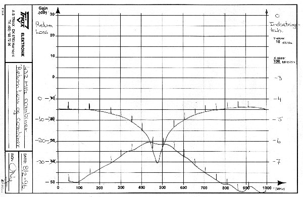
On 432 MHz the return loss is >20 dB (equal to VSWR 1.2:1). This is acceptable. But you can also see, that best match occurs around 470 MHz. This is probably caused by additional inductance from the connector centerpin in combination with the slightly different center conductor diameter. The splitter loss is 6.0 dB, exactly what theory says when a signal is split into four equal parts.