How to build a circular polarized cross element yagi from two identical yagis. This methode will work with any pair of well-behaved yagi's.
I have used TRIAX antennas bought through EDR (Experimenting Danish
Radioamateurs). The antennas comes with an integrated balun for connection
to 50 ohm coax.
On 2 meter I'm using two 8 element
yagi's to make an 8 + 8 element cross element yagi, and for 70 cm two
20 element yagi's to make an 18 + 18 element cross element yagi. (On 70 cm
I had to reduce the original triple element reflector to a single element
to avoid "interference" from the small metal boom holding the three
reflector elements)
The procedure was simply to take all elements from one antenna and mount
them at 90 degree angle on the other antenna's boom. But instead of placing
the new (vertical) element next to it's horizontal part, I have shifted
each element exactly one quater wavelength forward on the new boom. So the
entire vertical antenna is shifted forward with reference to the horizontal
antenna.
The forward shift is 514 mm for the 2 meter antenna and 172 mm for the 70 cm.
Of course you have to increase the original boom length by the same amount
- using bits of the boom from the stripped antenna.
When mounting the vertical elements watch out for horizontal and vertical
elements "colliding" with each other.
In my case the 70 cm antenna elements mounted without any problem - but on
the 2 meter version the horizontal 3'rd director and vertical 2'nd director
were only 5 mm from each other - not really possible with ø10 mm elements!
The solution was quite pragmatic, I just moved the two affected elements
4 mm back/forward. Such a small displacement from the designed position is not
critical from a practical standpoint.
The two antenna are feed through a splitter made from two 75 ohm quater wavelength coaxcable. See fig 1.

Traditionally circular polarization is generated by feeding two crossed dipoles 90 degrees out off phase. But you can also shift the dipoles 90 degrees (electrical) in space and feeding then in-phase with the same effect. The advantage is that the two cables in the splitter have equal length and therefore gives identical transformation of antenna impedance.
To understand the advantage of this, consider a situation where the dipoles are
not spaced form each other, but simply mounted together on the boom. One
antenna will have to be feed 90 off phase to the other - typical through a
quater wavelength piece of 50 ohm cable.
However if the two antennas are not exactly 50 ohm, this additional piece of
cable will transform the impedance from one of the antennas away from 50 ohm.
At the point where the two phasing cables are joined the impedance's from the
two individual antennas will be unequal, with the result that power is not
split equally between the two and polarization becomes elliptical. As an
example two antennas with SWVR of 1,2:1 will give an unbalance of 1,6 dB!
By shifting one section of the yagi forward by a quater wavelength the phasing cable to the two antennas becomes equal, impedances becomes equal and the antennas must share the power equally - regardless of the VSWR.
On 144 MHz a quater wavelength coax is 1/4 x 300/144 x 0,66 = 340 mm (solid
polyethylene dielectric). For practical reasons I use three quater wavelength
75 ohm cable, which gives the same transformation. The cablelength of 102 cm
allows the point where the three coax ends are joined to be put behind the
rear dipole.
For the same reason I've made the cables for the 70 cm antenna 340 mm long. The cable
must leave the antenna behind the rearmost reflector. I have also turned the dipoles,
so the cable entry is facing to the rear. (normally they are facing forward
towards the mastbracket)

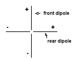
To achieve circular polarization the two dipoles - (which are offset by a quater wavelength in space) - are feed electrically in phase, and connected as shown on the drawing. The + sign indicates center conductor of the 75 ohm cables.
Connected this way you get Right Hand circular polarization - RHCP.
The opposite polarization - i.e Left Hand circular polarization - is made
by simply changing the cable connection to only one of the dipoles (+ to -)
or by adding an (electrical) halfwave cable to one of the dipoles.
The aerials are rather long - abt. 4 meter each. They have to be! If you want high gain only one thing really matters - boomlength. On my 2 meter beam the boom is sagging a bit and must be supported by an overhead support wire.
These two antennas have given me better signals to/from OSCAR-13 than anything before.
Back to OZ2OE homepage.