For several years I have been on the lookout for a used Power Meter - a HP432 or
similar. Then in Wienheim 1999 I came across the company Addcom Microwave from
the Nederlands offering surplus Power Heads N427A from General Microwaves (at
200,- DM). The power head contains the thermoelectric power sensor and the
necessary electronics for driving a 1 mA meter. So I only needed to add a simple
DC supply and a meter - together with a few modifications - to make myself a DC
to 12.4 GHz power meter with -20 dBm and -10 dBm range.
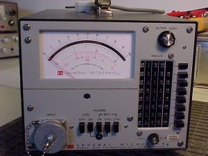
As I already had a powermeter with a defect! power probe (-you can always find defect power meters on flea markets - hi), the dual voltage DC supply and a 1 mA meter graduated in milliwatt was already in place.
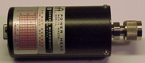
The Power Head:
The General Microwave power head is housed in a cylindrical can with male N-connector input and power supply and meter connections through a round multipin MIL connector in the back. The Power Head came with the following data sheet (179K).
The datasheet refers to N427B having 3 power ranges (0, -10 and -20 dBm). The N427A on the other hand is missing the 0 dBm range (no wires to pin G on the MIL connector). There is however a red wire to pin P, not shown in the diagram. DON'T use this. It connects directly to the very sensitive thermoelectric sensor and any experimenting with this wire has fatal consequences! - "been there - done that".
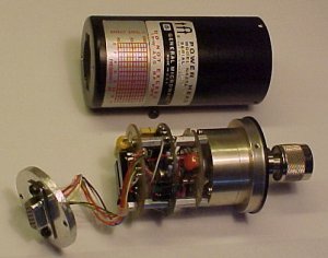
Modifications:
To open the unit first remove the big hexagonal nut holding the MIL connector in the back, then remove three screws at the front of the cylindrical can. You can now gently pull the electronics out of the can.
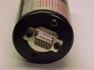
Change the MIL connector into something more "standard". I have used a 15 pin dataplug. Unsolder all wires and the two protecting diodes and move them to the new plug. As the plugs are quite different I had to make a round mounting plate from a piece of 4 mm aluminum, where the DB15 plug is mounted. This fits inside the black can and is held in place by two M3 screws tapped into the alu plate.
Now connect to the 1 mA meter/DC- supply according to the diagram, and the power
meter is finished.
Technical specifications:
- Thermoelectric Power Meter
- DC - 12.4 GHz
- - 20 dBm and - 10 dBm full scale range
- Accuracy 1%
Back to OZ2OE homepage.