Design of a 100 W Amplifier for 144 MHz using MRF317.
Background:
In the good old day's? when 2 meter multimode rig's only had 10 W output I wanted something more, and the idea of building a 100 W linear amplifier was obvious.So when I got hold of an MRF317 100 W 28 V transistor, I was ready to go!
The mechanical design:
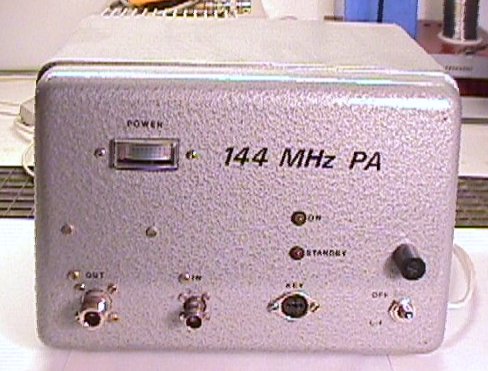
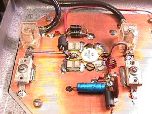
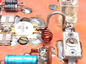
The amplifier is build into a metalbox measuring 240x160x160 mm. The space is mainly taken up by the 28 V / 7 A power supply. On the rear side of the box the amplifier is mounted against a big heat sink. The amplifier itself is build on a piece of double sided PCB about 140x100 mm. There is no PCB artwork, as I've simply cut out square islands with a knife, for soldering the transistor basis and collector and the terminals of the tuning capacitors. This is a fast and efficient way of building and it leaves an almost unbroken ground plane for the high RF return currents.The rest of the components are placed free standing above the board, as can be seen on the pictures.
The electrical design:
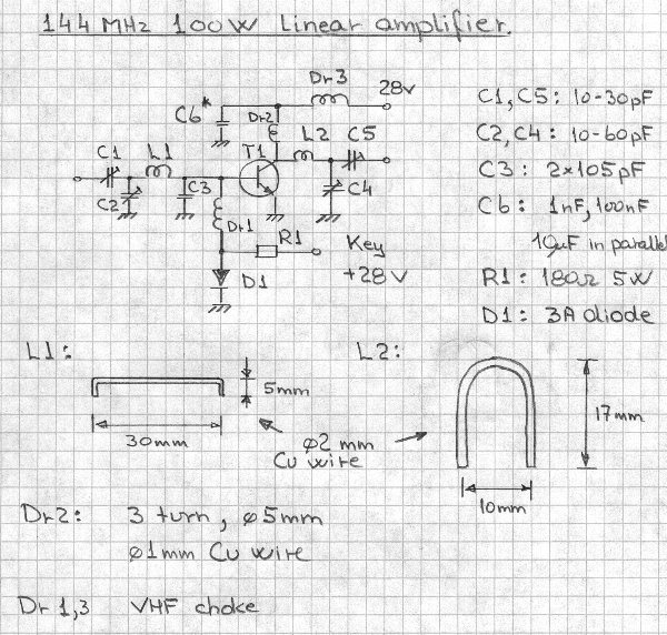
This amplifier is simplicity itself, as the diagram will show. Input and output circuits are calculated based on informations from the MRF317 datasheet, however as the data are for class C operation, and the amplifier is biased in class AB, the input circuit had to be optimised by experiments. It's important that C3 is placed close to the transistor and can handle the high RF currents at this point.
Bias circuit:
The transistor must be forward biased by applying 0.6 - 0.7 V to the basis. The actual forward bias voltage is adjusted (selected) by measuring the collector current. Normally I go for an idle current of 1/40 to 1/20 of the maximum collector current during full single tone output.In my experience the exact value of the idling current is uncritical.
This design uses a diode to produce the bias. By changing the current through
the diode (change value of resistor R1 to B+), the bias voltage can be "fine tuned".
This is a very simple bias circuit - with an undeserved bad reputation.
The problem is, that a wrongly designed bias circuit will not be able to supply
enough basecurrent during peak power. As a consequence the bias voltage
will drop and the transistor moves into class C, with the well known effects
of intermodulation and splatter!
However by selecting the right diode, enough current is available for the transistor.
My rule of thumb: - select a diode with a current rating of half the maximum
collector current of the transistor you're biasing. In this case I have chosen
a 3A diode.
The amplifier is keyed by applying 28 V to R1, this turns on the transistor. The collector can be left with 28 V also during receiving.
Testing the bias circuit:
Testing the bias is simple. Measure the base voltage - do it on the "cold" side of the basis choke. It will show maybe 0.65 V. Now apply drive power and watch the voltage drop as the DC base current increases. If the drop is less than 50 mV it's very fine, a drop of 100 mV is acceptable. But should the voltage drop increase further - the bias voltage may even go negative! - then there is not enough current available.You may find out that your state-of-the-art digital voltmeter "flips out" when trying to measure in the high RF field surrounding the amplifier. Hopefully you never junked that old analog multimeter - hi.
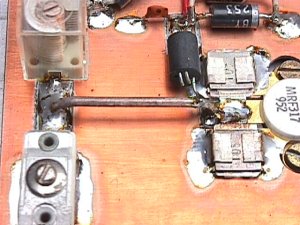
To increase the current capability of the bias circuit, you can chose a bigger diode, or put two diodes in parallel. Readjust the idle current and test again. As you can see on the pictures, I ended up using two diodes in parallel before being satisfied with the stability.
Results:
With 10 W drive and abt. 26 V supply voltage I have 90 W output. The transistor is designed for 28 V and will give more than 100 W, but I had to settle for a little less. The reason is, that my transformer/capacitors was a bit underrated and could not deliver max. current without ripple "break through". So by reducing the output voltage, the regulator had a little more headroom to work with.Back to OZ2OE homepage.