Design of a 10 GHz beacon antenna. A standard WG16 waveguide is used.
Principle:
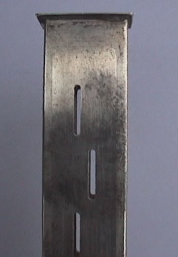
A slotted waveguide antenna works by radiating energy from the inside though a number of slots cut in the waveguide. Each slot acts as a (slotted) dipole, with the polarity opposite the direction of the slot. A vertical slot gives a horizontal polarisation.With many slots in a waveguide the antenna works like a stacked array of dipoles. More slots means more gain. And with slots on both sides the radiation pattern becomes (reasonably) omnidirectional.
The mechanical tolerances are more and more important when the frequency increases. On 10 GHz the wavelength is 30 mm, so an error of 1 mm is equivalent to a phase error of 12 deg. This is too much for a phased array, and all mechanical dimensions should thefore be accurate to less than 0.5 mm.
The design:
The upper end is equipped with 2 times 8 slots on each broad side - this is the radiating section. In the lower end is the coax to waveguide transition and the tuning screws for optimising the return loss (VSWR). The two ends are closed (shorted) by pieces of brass soldered to the waveguideThe waveguide between the two sections must be more than 1 wavelength long to ensure a well behaved field before the radiating section. Otherwise the middle section can be as long as you want for mechanical or electrical reasons (keeping the radiating end free of obstacles).
Documentation:
Drawing of radiating section.
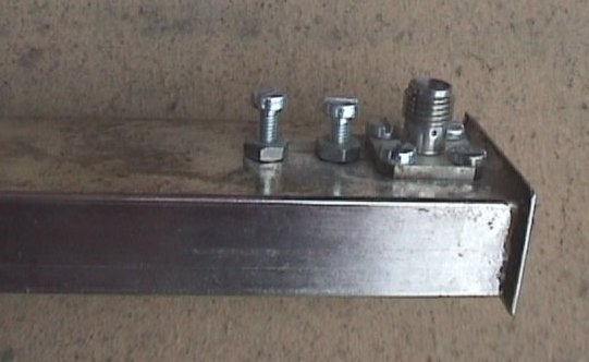
Drawing af coax to waveguide transition.
Calculations of waveguide slot antenna.
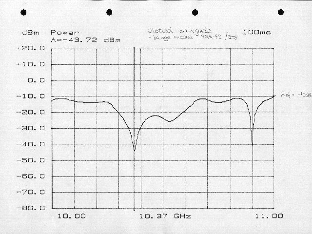
Return loss.
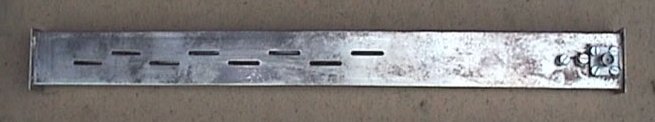
Picture of antenna. Picture of SMA transition. Detailled picture of slots.
Technical specifications:
- Omnidirectional waveguide slot antenna
- 2 x 8 slots
- Frequency 10368 - 10370 MHz
- 10 dB gain
- Return loss -30 dB (VSWR 1.06:1)
Back to OZ2OE homepage.